Great thanks to ERNW for the translation of the article!
(Original article was published on https://xakep.ru/2014/11/24/research-hyper-v and https://xakep.ru/2015/01/05/hyper-v-research-part-2)
Root-section (parent partition, root OS) - Windows Server 2012 R2 with the included component of Hyper-V;
(Original article was published on https://xakep.ru/2014/11/24/research-hyper-v and https://xakep.ru/2015/01/05/hyper-v-research-part-2)
Root-section (parent partition, root OS) - Windows Server 2012 R2 with the included component of Hyper-V;
Guest operating systems - virtual machine Hyper-V installed Windows Server 2012 R2;
TLFS – Hypervisor Top-Level Functional Specification: Windows Server 2012 R2;
LIS – Linux Integration Services
Finding a bug, which later received the number MS13-092 (error component Hyper-V Windows Server 2012 allows you to send a hypervisor in BSOD from the guest operating system or run arbitrary code in other guest operating systems which are running on a vulnerable host server), it was very unpleasant surprise for Microsoft Engineers. Before that, for almost three years, no one has discovered a vulnerability in Hyper-V. It was only the MS10-102, which were found at the end of 2010. During those four years, the popularity of cloud services increased greatly, and researchers are more and more interested in security hypervisor underlying cloud systems. (Another bug MS15-042 was fixed but there is no detailed overview of this).
However, the number of publicly available work is low: the researchers are reluctant to spend their time exploring such complex and poorly documented architectural solutions. This article does not describe the specific vulnerabilities of the hypervisor, but it should shed light on the inner workings of Hyper-V, and thereby partially simplify future research.
This article will describe some features of the hypervisor, in particular the component of the vmbus message processing mechanism using the steal a hypervisor mechanism. (Before reading the article, it is recommended to get acquainted with the report from ERNW (http://goo.gl/1Cvotv), «Hyper-V debugging for beginners» (http://hvinternals.blogspot.com/2015/10/hyper-v-debugging-for-beginners.html), and Hypervisor TLFS (http://goo.gl/9dISj7)
At the time of writing the article the used Hyper-V server and guest OS was Windows Server 2012 R2 Update 1 (machine type-1 Generation), but to reflect some of the features of the components we´ve used other versions of the Windows operating system, which will be stated in this article. For a test environment, you have to deploy the VMware Workstation 12.
1.VMBUS
In a nutshell the VMBUS is a technology of interaction between the guest operating systems and root OS accordingly.
There are components in the guest and root OS that implements this interaction through the interfaces provided by the hypervisor and described in TLFS 4.0(a). Microsoft developed the components for Linux-like guest operating systems, which are already integrated into the kernel (https:/github. com/LIS).
Starting with Windows Server 2008, the Windows kernel functions were optimized for the operating system in a virtual environment Hyper-V. For comparison, in the core of Windows Server 2008 (x64) are 25 functions implemented with the prefix Hvl, which identifies them as belonging to a library to integrate with the hypervisor. Windows Server 2012 R2 has 109 Hvl-functions already. Windows Server 2016 TP2 has 12 Hvi-functions and 230 Hvl-functions.
Consider, how the components of VMBUS interacts with the hypervisor, root and guest OS. First look into the source code of LIS and see that the VMBUS is a device which supports ACPI. ACPI devices can be viewed by using the ACPI Utility tool, included in the AIDA64 version 3. XX (later it was removed). With its help in SB_.PCI0.SBRG it detected 2 devices: VMB8 and VMBS.

Dump ACPI DSDT table that contains information on peripheral devices and functions of the hardware platform, using the same tools and ACPI Tool to decompile AML-disassembler (http://goo.gl/1pOZPX) in ASL. We obtain:

A superficial reading of ACPI Specification 5.0 made it clear that if the guest OS is Windows 6.2 and higher, the device will consume VMB8, otherwise VMBS. The only difference between these devices is the presence of an object _UID (UniqID), which is present in the VMB8. According to the ACPI specification, the presence of that object in the table is optional and is only required if the device can not present to operating system permanent unique ID. Also became a known resources that used by device - interrupt 5 and 7.
For comparison, in the virtual machine type Generation 2 there are only the devices VMBS placed in _SB_. VMOD. VMBS, (but with the object _UID) which using only interrupt 5:
Routines, that dispatch interrupts, register in interrupt dispatch table (IDT). Meanwhile we found on ACPI DSDT IRQ 5 and 7 that the handlers in the IDT having no direct connection, and to compare its interruption handler, Windows uses the referee interrupts (generally, there are several classes of arbitrators, in addition IRQ, - DMA, I / O, memory). All about the arbitrators can be found in the MSDN blog (http://goo.gl/FuvG4R, http://goo.gl/V3UV8e, http://goo.gl/h1vXaf)
Information about registered arbitrators can be seen in WinDBG with the command !acpiirqarb.
kd> !acpiirqarb – for the Guest Windows Server 2012 R2 Gen1:

The output shows that the IRQ 7 address handler that will be in the 0x71 cell of IDT, for IRQ 5 - 0x81. Generation numbers interrupt handlers are using the acpi!ProcessorReserveIdtEntries function at the stage of construction of the device tree PnP-manager, when the functional device driver is not already loaded. Register ISR in the IDT has been going in the later stages, for example, when the device driver procedure IoConnectInterrupt will be executed. However, looking at the elements of IDT, we see that the ISR for the interrupt of 0x71 and 0x81 is not registered:
kd> !idt -a
…………………………………………………………………………………………………………………………….
71: fffff80323f73938 nt!KxUnexpectedInterrupt0+0x388
81: fffff80323f739b8 nt!KxUnexpectedInterrupt0+0x408
…………………………………………………………………………………………………………………………….
In Windows Server 2012 R2 Gen2 for IRQ 5 was mapped 0x90 the IDT.
kd> !acpiirqarb – for guest Windows Server 2012 R2 Gen2
Processor 0 (0, 0):
Device Object: 0000000000000000
Current IDT Allocation:
0000000000000000 - 0000000000000050 00000000 <Not on bus> A:0000000000000000 IRQ(GSIV):10
0000000000000090 - 0000000000000090 D ffffe001f35eb520 (vmbus) A:ffffc00133972660 IRQ(GSIV):5
…………………………………………………………………………………………………………………………….
ISR -procedure for interrupt 0x90 also is not defined:
kd> !idt -a
90: fffff8014a3daa30 nt!KxUnexpectedInterrupt0+0x480
In Windows 8.1x86 we see a slightly different picture
kd> !acpiirqarb – for Windows 8.1 x86
Processor 0 (0, 0):
Device Object: 00000000
Current IDT Allocation:
…………………………………………………………………………………………………………………………….
0000000000000081 - 0000000000000081 D 87f2f030 (vmbus) A:881642a8 IRQ(GSIV):fffffffe – such values are generally associated with MSI-devices.
…………………………………………………………………………………………………………………………….
00000000000000b2 - 00000000000000b2 S B 87f31030 (s3cap) A:8814b840 IRQ(GSIV):5
In addition, for interrupt number 0x81 ISR-defined procedure vmbus!XPartPncIsr:
kd> !idt
81: 81b18a0c vmbus!XPartPncIsr (KINTERRUPT 87b59e40)
b2: 81b18c58 nt!KiUnexpectedInterrupt130
s3cap - auxiliary driver to work with Hyper-V emulated video card S3 Trio.

Thus ISR vmbus! XPartPncIsr registered in the IDT only in Windows 8.1 x86 (presumably in other x86 operating systems that support Microsoft as a guest operating system for Hyper-V, using the same method). Procedure vmbus!XPartPncIsr used for handling interrupts is generated by the hypervisor.
In x 64-bit systems, starting with Windows 8 \ Windows Server 2012, integration with the hypervisor is implemented slightly differently. In the IDT system and interrupt handlers have been added which were generated by the hypervisor. Let us briefly consider how the IDT is formed at the stage of Windows loading.
After initialization the Windows loader winload.efi IDT looks as follows (output of the script pykd from a WinDBG breakpoint in winload.efi during the boot process with the parameter / bootdebug):
kd> !py D:\hyperv4\idt_winload_parse.py
isr 1 address = winload!BdTrap01
isr 3 address = winload!BdTrap03
isr d address = winload!BdTrap0d
isr e address = winload!BdTrap0e
isr 29 address = winload!BdTrap29
isr 2c address = winload!BdTrap2c
isr 2d address = winload!BdTrap2d
then during winload!OslArchTransferToKernel IDT is cleared and control is passed to the kernel of Windows, where a function nt!KiInitializeBootStructures initialized IDT with the values from the table KiInterruptInitTable:
kd> dps KiInterruptInitTable L40
……………………………………………………………………………………….
fffff800`1b9553c0 00000000`00000030
fffff800`1b9553c8 fffff800`1b377160 nt!KiHvInterrupt
fffff800`1b9553d0 00000000`00000031
fffff800`1b9553d8 fffff800`1b3774c0 nt!KiVmbusInterrupt0
fffff800`1b9553e0 00000000`00000032
fffff800`1b9553e8 fffff800`1b377810 nt!KiVmbusInterrupt1
fffff800`1b9553f0 00000000`00000033
fffff800`1b9553f8 fffff800`1b377b60 nt!KiVmbusInterrupt2
fffff800`1b955400 00000000`00000034
fffff800`1b955408 fffff800`1b377eb0 nt!KiVmbusInterrupt3
……………………………………………………………………………………….
Accordingly, handlers traps 0x30-0x34 IDT after the initialization would look similar to the following:
kd> !idt
……………………………………………………………………………………….
30: fffff8001b377160 nt!KiHvInterrupt
31: fffff8001b3774c0 nt!KiVmbusInterrupt0
32: fffff8001b377810 nt!KiVmbusInterrupt1
33: fffff8001b377b60 nt!KiVmbusInterrupt2
34: fffff8001b377eb0 nt!KiVmbusInterrupt3
……………………………………………………………………………………….
What's interesting, the second generation of the virtual machine can be only created on the basis of operating systems when the kernel containing these 5 additional handlers. In order to generate interrupts Intel has a hardware feature "virtual interrupt delivery", but Hyper-V does not use the opportunity to transfer control to these handlers. Instead, the hypervisor activates bit corresponding to the number of the vector in the special memory area by using instructions locks bts [rcx + 598h], rax, where in rax - interrupt vector number (0x30-0x32), so perhaps developers of Hyper-V considered an option with the registration procedure vmbus!XPartPncIsr handler as less productive solution than the option of the interrupt generation by the APIC virtualization from the data in the virtual registers SINTx.
These handlers are registered with IDT, even when the operating system runs out of the Hyper-V environment. Each handler calls HvlRouteInterrupt, passing the
index as a parameter.

HvlRouteInterrupt:
This function calls a handler from an array of pointers HvlpInterruptCallback depending of value of the index. An array in the root OS looks as follows:
5: kd> dps HvlpInterruptCallback
fffff802`fff5cc30 fffff800`dc639d50 winhvr!WinHvOnInterrupt
fffff802`fff5cc38 fffff800`dd5a9ec0 vmbusr!XPartEnlightenedIsr
fffff802`fff5cc40 fffff800`dd5a9ec0 vmbusr!XPartEnlightenedIsr
fffff802`fff5cc48 fffff800`dd5a9ec0 vmbusr!XPartEnlightenedIsr
fffff802`fff5cc50 fffff800`dd5a9ec0 vmbusr!XPartEnlightenedIsr
fffff802`fff5cc58 00000000`00000000
XPartEnlightenedIsr on index, passed from KiVmbusInterruptX, adds to the DPC queue of one of two possible functions from the array of DPC structures in vmbusr: vmbusr! ParentInterruptDpc or vmbusr! ParentRingInterruptDpc:

The number of 2 elements DPC structures (one for nt!KiVmbusInterrupt0, second – nt!KiVmbusInterrupt1) in the array is determined by the function vmbusr!XPartPncPostInterruptsEnabledParent and depends on the number of logical processors in the root OS. DPC is added for each logical processor with deferred routines vmbusr!ParentInterruptDpc and vmbusr!ParentRingInterruptDpc. Function vmbusr!ParentRingInterruptDpc defines the address of KDPC-stucture for the nt!KeInsertQueueDpc based on the fact on which the processor is currently executing.
In a Windows guest OS, vmbus registers in the array HvlpInterruptCallback only one handler:
1: kd> dps HvlpInterruptCallback
fffff803`1d171c30 fffff800`6d7c5714 winhv!WinHvOnInterrupt
fffff803`1d171c38 fffff800`6d801360 vmbus!XPartEnlightenedIsr
fffff803`1d171c40 00000000`00000000
Array HvlpInterruptCallback is filled by function nt!HvlRegisterInterruptCallback. Handler WinHvOnInterrupt is registered during loading winhvr.sys (winhvr! WinHvpInitialize-> winhvr! WinHvReportPresentHypervisor-> winhvr! WinHvpConnectToHypervisor-> nt! HvlRegisterInterruptCallback).
The rest of the 4 handler registered by vmbusr.sys when it loads by PnPManager (vmbusr! RootDevicePrepareHardwareParent-> nt! HvlRegisterInterruptCallback).
Let's try to understand how the hypervisor passes the control to the system interrupt handlers which were described above. To do this, you must refer to the Virtual Interrupt Control TLFS. In short, the Hyper-V manages interrupt in the guest OS through a synthetic interrupt controller (SynIC), which is an extension of the local APIC and uses an extra set of registers displayed in the memory (memory mapped registers). Each virtual processor in addition to the usual APIC has additional SynIC. SynIC contains 2 pages: SIM (synthetic interrupt message) and SIEF(synthetic interrupt event flags), SIEF and SIM are arrays of 16 elements, the element size - 256 bytes. The physical address (to be more precise, the Guest Physical Address) of these arrays are located in the MSR-registers SIEF and SIMP respectively. The addresses of these pages for each logical CPU would be different. Also for SynIC defined 16 SINTx-registers. Each of the array elements in SIM and SIEF compared with the corresponding register SINTx. WinDBG shows the contents of the SINTx registers using the !apic command (since WinDBG 6.3).
Root ОS:

Guest OS:
Configuration of registers SINT0 and SINT1 are performed by the function nt!HvlEnlightenProcessor by recording the parameters in MSR 40000090h and 40000091h respectively. SINT4 and SINT5 are configured in vmbusr.sys: vmbusr!XPartPncPostInterruptsEnabledParent-> winhvr!WinHvSetSint-> winhvr!WinHvSetSintOnCurrentProcessor. SINT2 in the guest operating system is configured in vmbus.sys which called winhv!WinHvSetSintOnCurrentProcessor.
Each SINTx present 8-bit field Vector which impact on the interrupt routine will be given control when the hypercall is executed with the parameters set by PortID (HvSignalEvent, HvPostMessage).
SINTx can be specified explicitly (for example, message interception will always be controlled by SINT0 and placed in the first element of the page SIM), clearly (for timer message) or configured for a port that was created with the HvCreatePort hypercall, which has parameter PortTypeInfo. If the port type is HvPortTypeMessage or HvPortTypeEvent, the PortTypeInfo parameter is TargetSint, which contains SINT number that you want to bind the port to and the value can be from 1 to 15 (SINT0 is reserved for messages from the hypervisor and cannot be specified as a TargetSint, when you create a port).
Analyze of non-zeroed SINT values in root OS show that there are 3 (from 5) interrupt routine was used (KiHvInterrupt, KiVmbusInterrupt0, KiVmbusInterrupt1). Maybe KiVmbusInterrupt2 and KiVmbusInterrupt3 need to run the servers with a large number of logical processors (eg, 64), but, unfortunately, in a test environment, this version could not be verified. Also, in the values of the SINTx registers can be seen that the handler nt!KiHvInterrupt (vector 30) will be called as when generating an interrupt from the hypervisor and ports by the parameter when TargetSint is equal to 1.
For example, consider the parameters of the ports that are created when you activate each of the services from the guest Hyper-V integration components.
In the following table are sample values of some parameters of the hypervisor HvCreatePort:

Root OS and guest OS interaction during work Integration Services occurs through the 5-th element of the array SIEF, I.e. the handler in root OS will call KiVmbusInterrupt1.
The number of each port should be created equal to the previous and increased by 1. That is, If you disable all services integration and then re-enable them, the port numbers that are created for these services will be in the range from 0x22 to 0x27 (the configuration is shown in Figure 11, in other cases, the port number are of course different).
You can see the port settings if you connect directly to the hypervisor debugger and trace the passed data to the handler of the hypervisor HvCreatePort or connect the kernel debugger and trace the parameters WinHvCreatePort in the driver winhvr.sys.
The other ports are created when you power on guest OS (number of ports depends on the configuration of the guest operating system). The numbering is given by the order they are created if you enabled the virtual machine port in Windows Server 2012 R2 hardware by default.

It is important to note the fact that the SIM0 slot in the guest and the parent OS is reserved for transmitting messages from the hypervisor. The format of these messages is documented in TLFS. When data is transferred over the remaining slots it will uses a different data format message. Vmbus messages is not documented, but the necessary information to work with them is present in LIS source codes.
Some information about the vmbus messages processing by vmbusr.sys:

vmbusr!ChReceiveChannelMessage handles such messages in root OS handles and analyzes the contents of the 4th slot SIM and determines code of vmbus messages. If it is 0 (CHANNELMSG_INVALID) or greater than 0x12, then the function returns an error code 0xC000000D (STATUS_INVALID_PARAMETER). Otherwise, the function processes the transmitted guest or root OS communication. For example, when the component Guest Services is enabled root OS sends a message CHANNELMSG_OFFERCHANNEL to the Guest OS, in response to the guest OS sends CHANNELMSG_GPADL_HEADER, then the root OS sends CHANNELMSG_GPADL_CREATED, gets back a message CHANNELMSG_OPENCHANNEL and finally sends a message CHANNELMSG_OPENCHANNEL_RESULT to the guest OS with the result code of the operation to create a channel. It is worth noting that prior to the treatment of each valid message function ChReceiveChannelMessage checks sent message (ChpValidateMessage), in particular on the subject of who is the sender (root-OS or guest OS) and for the minimum size of the message body.
Let's see what the messages are exchanged between root OS and the guest OS. To do this, write a driver that replaces the address of an array of handlers HvlpInterruptCallback in the root operating system on their own handlers.
The driver is written in Visual Studio 2013. It must be loaded into the root OS, for example, by OSRLoader. To send IOCTL-code it uses a simple program SendIOCTL.exe. After sending IOCTL-code INTERRUPT_CODE the driver starts to perform and processing the data sent by the hypervisor to slot SIM0. Unfortunately the variable HvlpInterruptCallback, which contains the address of an array of pointers for the message handlers, is not exported by windows kernel, so it is necessary to analyze the code of the detection exported by the kernel function HvlRegisterInterruptCallback. It does contain the necessary address of the array. Also, unfortunately, it will not simply work to call HvlRegisterInterruptCallback to register your message handler, as in the beginning of the function it goes to check the variable values of HvlpFlags. If the variable is equal to 1 (as it is the assigned value in the initial stages of loading the kernel), the function stops the execution and returns an error code 0xC00000BB (STATUS_NOT_SUPPORTED), respectively, to register the handler correctly, you will need to replace the handler with your own version of the HvlpInterruptCallback function. The Hyperv4 driver required activities are performed by RegisterInterrupt.
Function RegisterInterrupt driver hyperv4 performs.
int RegisterInterrupt()
{
UNICODE_STRING uniName;
PVOID pvHvlRegisterAddress = NULL;
PHYSICAL_ADDRESS pAdr = {0};
ULONG i,ProcessorCount;
// We get the number of active processor cores
ProcessorCount = KeQueryActiveProcessorCount(NULL);
// search for addresses of the exported function HvlRegisterInterruptCallback
DbgLog("Active processor count",ProcessorCount);
RtlInitUnicodeString(&uniName, L"HvlRegisterInterruptCallback");
pvHvlRegisterAddress = MmGetSystemRoutineAddress(&uniName);
if (pvHvlRegisterAddress == NULL){
DbgPrintString("Cannot find HvlRegisterInterruptCallback!");
return 0;
}
DbgLog16("HvlRegisterInterruptCallback address ",pvHvlRegisterAddress);
// search for addresses Variable HvlpInterruptCallback
FindHvlpInterruptCallback((unsigned char *)pvHvlRegisterAddress);
// replacement of original manufacture handler to our handler
ArchmHvlRegisterInterruptCallback((uintptr_t)&ArchmWinHvOnInterrupt, (uintptr_t)pvHvlpInterruptCallbackOrig, WIN_HV_ON_INTERRUPT_INDEX);
ArchmHvlRegisterInterruptCallback((uintptr_t)&ArchXPartEnlightenedIsr, (uintptr_t)pvHvlpInterruptCallbackOrig, XPART_ENLIGHTENED_ISR0_INDEX);
ArchmHvlRegisterInterruptCallback((uintptr_t)&ArchXPartEnlightenedIsr, (uintptr_t)pvHvlpInterruptCallbackOrig, XPART_ENLIGHTENED_ISR1_INDEX);
ArchmHvlRegisterInterruptCallback((uintptr_t)&ArchXPartEnlightenedIsr, (uintptr_t)pvHvlpInterruptCallbackOrig, XPART_ENLIGHTENED_ISR2_INDEX);
ArchmHvlRegisterInterruptCallback((uintptr_t)&ArchXPartEnlightenedIsr, (uintptr_t)pvHvlpInterruptCallbackOrig, XPART_ENLIGHTENED_ISR3_INDEX);
//because SIMP value for all processor cores are different, you must obtain the addresses of all SIM,
//make it possible to access the contents of the page using MmMapIoSpace.
//and save the received virtual address of each page in the array for later
for (i = 0; i < ProcessorCount; i++){
KeSetSystemAffinityThreadEx(1i64 << i);
DbgLog("Current processor number", KeGetCurrentProcessorNumberEx(NULL));
pAdr.QuadPart = ArchReadMsr(HV_X64_MSR_SIMP) & 0xFFFFFFFFFFFFF000;
pvSIMP[i] = MmMapIoSpace(pAdr, PAGE_SIZE, MmCached);
if (pvSIMP[i] == NULL){
DbgPrintString("Error during pvSIMP MmMapIoSpace");
return 1;
}
DbgLog16("pvSIMP[i] address", pvSIMP[i]);
pAdr.QuadPart = ArchReadMsr(HV_X64_MSR_SIEFP) & 0xFFFFFFFFFFFFF000;
pvSIEFP[i] = MmMapIoSpace(pAdr, PAGE_SIZE, MmCached);
if (pvSIEFP[i] == NULL){
DbgPrintString("Error during pvSIEFP MmMapIoSpace");
return 1;
}
DbgLog16("pvSIEFP address", pvSIEFP[i]);
}
return 0;
}
HvlpInterruptCallback after the execution of the function RegisterInterrupt (in case the replace all handlers at the same time) is as follows:
kd> dps HvlpInterruptCallback
fffff800`5a9ccc30 fffff800`4e9cc0a9 hyperv4!ArchmWinHvOnInterrupt
fffff800`5a9ccc38 fffff800`4e9cc0e3 hyperv4!ArchXPartEnlightenedIsr
fffff800`5a9ccc40 fffff800`4e9cc0e3 hyperv4!ArchXPartEnlightenedIsr
fffff800`5a9ccc48 fffff800`4e9cc0e3 hyperv4!ArchXPartEnlightenedIsr
fffff800`5a9ccc50 fffff800`4e9cc0e3 hyperv4!ArchXPartEnlightenedIsr
fffff800`5a9ccc58 00000000`00000000
(However, during experiments involving intensive virtual machine, it is better to replace one handler because replacing all at once leads to system instability)
Replacement is similar to the original code: one handler for hypervisor and four handlers for processing messages from the vmbus. Procedures ArchmWinHvOnInterrupt and ArchXPartEnlightenedIsr save all registers on the stack and passed to the parse functions ParseHvMessage and ParseVmbusMessage respectively (mPUSHAD and mPOPAD macros that perform saving registers on the stack):
ArchmWinHvOnInterrupt PROC
mPUSHAD
call ParseHvMessage
mPOPAD
mov rdx,pvWinHVOnInterruptOrig
jmp rdx
ArchmWinHvOnInterrupt ENDP
ArchXPartEnlightenedIsr PROC
mPUSHAD
call ParseVmbusMessage
mPOPAD
mov rdx,pvXPartEnlightenedIsrOrig
jmp rdx
ArchXPartEnlightenedIsr ENDP
After parsing, the control is passed to the original procedure WinHvOnInterrupt and XPartEnlightenedIsr. Parsing function is as follows:
void ParseHvMessage()
{
PHV_MESSAGE phvMessage, phvMessage1;
// get the number of the active logical processors
ULONG uCurProcNum = KeGetCurrentProcessorNumberEx(NULL);
if (pvSIMP[uCurProcNum] != NULL){
phvMessage = (PHV_MESSAGE)pvSIMP[uCurProcNum];
} else{
DbgPrintString("pvSIMP is NULL");
return;
}
// notification message is sent through the 1st SIM slot
phvMessage1 = (PHV_MESSAGE)((PUINT8)pvSIMP[uCurProcNum] + HV_MESSAGE_SIZE); //for SINT1
if (phvMessage1->Header.MessageType != 0){
DbgPrintString("SINT1 interrupt");
}
//depending on the type of message handlers call procedures
//patterns for each message type are described in TLFS
switch (phvMessage->Header.MessageType)
{
case HvMessageTypeX64IoPortIntercept:
PrintIoPortInterceptMessage(phvMessage);
break;
case HvMessageTypeNone:
DbgPrintString("HvMessageTypeNone");
break;
case HvMessageTypeX64MsrIntercept:
PrintMsrInterceptMessage(phvMessage);
break;
case HvMessageTypeX64CpuidIntercept:
PrintCpuidInterceptMessage(phvMessage);
break;
case HvMessageTypeX64ExceptionIntercept:
PrintExceptionInterceptMessage(phvMessage);
break;
default:
DbgLog("Unknown MessageType", phvMessage->Header.MessageType);
break;
}
}
The function gets the number of active logical processor, the address of the page SIM and reads the value of the zero slots SIM it will first analyze the message type phvMessage->Header.MessageType, because the message body for each type is different. In DbgView you can see the following picture:

void ParseVmbusMessage(size_t index)
{
// get the number of the active logical processor
ULONG uCurProcNum = KeGetCurrentProcessorNumberEx(NULL);
PHV_MESSAGE phvMessage4;
PVMBUS_MESSAGE pvmbMessage;
if (pvSIMP[uCurProcNum] != NULL){
// get the pointer to the 4-th slot SIM
phvMessage4 = (PHV_MESSAGE)((PUINT8)pvSIMP[uCurProcNum] + HV_MESSAGE_SIZE * 4);
//DbgLog("Hv interrupt vector index", index);
// If the message type is not HvMessageTypeNone the Payload contains the vmbus message
if (phvMessage4->Header.MessageType != HvMessageTypeNone){
pvmbMessage = (PVMBUS_MESSAGE)phvMessage4->Payload;
// analyze the message and perform the vmbus type parsing
// structure the vmbus of messages are described in LIS
switch (pvmbMessage->vmbHeader.msgtype)
{
case CHANNELMSG_GPADL_HEADER:
ParseGpadlHeaderMessage(pvmbMessage);
break;
case CHANNELMSG_OPENCHANNEL:
ParseOpenChannelMessage(pvmbMessage);
break;
default:
DbgLog("Unhandled vmbus message", pvmbMessage->vmbHeader.msgtype);
break;
}
}
}
else{
DbgPrintString("Error.pvSIMP is NULL");
return;
}
}
The function gets the number of active logical processor, addresses of the SIM and get value of SIM4. For example, disassembled for the type of message and CHANNELMSG_OPENCHANNEL and CHANNELMSG_GPADL_HEADER, but in LIS you can see the format of all types of messages. Messages for vmbus usually generated when turn on/turn off the virtual machine, or one of the components of Integration Services. For example, when you enable the Data Exchange feature, in the debugger you will see the following message:
Integration Services - Data Exchange
Next, consider what image data is exchanged between the guest OS and his parents by the example of one of the Integration Services components - Data Exchange. This component allows the root OS to read data from a particular registry keys in the guest OS. (For information about the technology KvP again can be found in the msdn blog: http://goo.gl/R0U52l, http://goo.gl/8rVeNA).
To verify this in the guest OS we will create the key HKEY_LOCAL_MACHINE\SOFTWARE\Microsoft\Virtual Machine\Guest key with a value of "KvPDataValue".
To get the value of the key in the root OS the following PowerShell script has been used:
$vm = Get-WmiObject -Namespace root\virtualization\v2 -Class Msvm_ComputerSystem -Filter {ElementName = 'Windows Server 2012 R2 Gen1'}
$vm.GetRelated("Msvm_KvpExchangeComponent").GuestExchangeItems | % { $GuestExchangeItemXml = ([XML]$_).SelectSingleNode("/INSTANCE/PROPERTY[@NAME='Name']/VALUE[child::text() = 'KvPDataKey']")
if ($GuestExchangeItemXml -ne $null)
{
$GuestExchangeItemXml.SelectSingleNode("/INSTANCE/PROPERTY[@NAME='Data']/VALUE/child::text()").Value
}
}
The script will return the value of the key KvPDataKey::
Note that even though that the script gets all the available set of values by using the
$vm.GetRelated("Msvm_KvpExchangeComponent").GuestExchangeItems and only after it parses every object for key KvPDataKey. Accordingly the script will work only when the component Data Exchange is enabled in the virtual machine properties.
When you activate a component Data Exchanger root OS through hypercall HvPostMessage guest OS sends a message with the code CHANNELMSG_OFFERCHANNEL:
WINDBG>dd @rcx – rcx is the input parameter for the hypercall HvPostMessage
00000080`002ff000 00000001 00000000 00000001 000000c4
00000080`002ff010 00000001 00000000 a9a0f4e7 4d965a45
00000080`002ff020 848a27b8 e6038c1e 242ff919 418007db
00000080`002ff030 6cb82e9c 558c8cb6 00000000 00000000
00000080`002ff040 00000000 00000000 00000011 00000004
You can draw attention to the fact that the data containing the GUID of the device is connected to the vmbus, as a child device:
WINDBG>!devnode \Driver\vmbus
Dumping IopRootDeviceNode (= 0xffffe0002bd2ed30)
DevNode 0xffffe0002bd2ed30 for PDO 0xffffe0002bd2fe50
WINDBG>!devnode 0xffffe0002bd2ed30 1 vmbus
………………………………………………………………………………
DevNode 0xffffe0002c03cd30 for PDO 0xffffe0002c00db00
InstancePath is "VMBUS\{a9a0f4e7-5a45-4d96-b827-8a841e8c03e6}\{242ff919-07db-4180-9c2e-b86cb68c8c55}"
State = DeviceNodeStarted (0x308)
Previous State = DeviceNodeEnumerateCompletion (0x30d)
………………………………………………………………………………
After this function is called in guest OS vmbus!InstanceDeviceControl The entire stack looks like this:
WINDBG>kс
Call Site
nt!IoAllocateMdl
vmbus!InstanceCloseChannel+0x22d (return to function without symbol name)
vmbus!InstanceDeviceControl+0x118
Wdf01000!FxIoQueue::DispatchRequestToDriver+0x1be
Wdf01000!FxIoQueue::DispatchEvents+0x363
Wdf01000!FxIoQueue::QueueRequest+0x8d
Wdf01000!FxDevice::DispatchWithLock+0xb51
vmbkmcl!KmclpSynchronousIoControl+0xa7
vmbkmcl!KmclpClientOpenChannel+0x2a6
vmbkmcl!KmclpClientFindVmbusAndUnlock+0x162
vmbkmcl!VmbChannelEnable+0x231
vmbus!PipeStartChannel+0x9e
vmbus!PipeAccept+0x81
vmbus!InstanceCreate+0x90
Wdf01000!FxFileObjectFileCreate::Invoke+0x3f
Wdf01000!FxPkgGeneral::OnCreate+0xb16
Wdf01000!FxPkgGeneral::Dispatch+0x3d9
Wdf01000!FxDevice::DispatchWithLock+0x7d8
nt!IopParseDevice+0x7b3
nt!ObpLookupObjectName+0x6d8
nt!ObOpenObjectByName+0x1e3
nt!IopCreateFile+0x372
nt!NtCreateFile+0x78
nt!KiSystemServiceCopyEnd+0x13
ntdll!NtCreateFile+0xa
KERNELBASE!CreateFileInternal+0x30a
KERNELBASE!CreateFileW+0x66
vmbuspipe!VmbusPipeClientOpenChannel+0x44
icsvc!ICTransportVMBus::ClientNotification+0x60
vmbuspipe!VmbusPipeClientEnumeratePipes+0x1ac
icsvc!ICTransportVMBusClient::Open+0xe5
icsvc!ICEndpoint::Connect+0x66
icsvc!ICChild::Run+0x65
icsvc!ICKvpExchangeChild::Run+0x189
icsvc!ICChild::ICServiceWork+0x137
icsvc!ICChild::ICServiceMain+0x8f
svchost!ServiceStarter+0x358
sechost!ScSvcctrlThreadA+0x25
KERNEL32!BaseThreadInitThunk+0xd
ntdll!RtlUserThreadStart+0x1d
IoAllocateMdl is called with the size of the buffer to allocate 0xC000. The result is a structure formed by MDL:
WINDBG>dt nt!_MDL @rax (в rax - ffffe001`51d0d0d0)
+0x000 Next : (null)
+0x008 Size : 0n144
+0x00a MdlFlags : 0n8
+0x00c AllocationProcessorNumber : 0
+0x00e Reserved : 0xffff
+0x010 Process : (null)
+0x018 MappedSystemVa : 0xffffe001`514e684c Void
+0x020 StartVa : 0xffffd000`bb193000 Void
+0x028 ByteCount : 0xc000
+0x02c ByteOffset : 0
It then calls the MmProbeAndLockPages, then mdl structure is complemented by elements of the pfn.
WINDBG>dq ffffe001`51d0d0d0 L20
ffffe001`51d0d0d0 00000000`00000000 ffff0000`008a0090
ffffe001`51d0d0e0 00000000`00000000 ffffe001`514e684c
ffffe001`51d0d0f0 ffffd000`bb193000 00000000`0000c000
ffffe001`51d0d100 00000000`0002d5bb 00000000`0002d5bc
ffffe001`51d0d110 00000000`0002d5bd 00000000`0002d5be
ffffe001`51d0d120 00000000`0002d5bf 00000000`0002d5c0
ffffe001`51d0d130 00000000`0002d5c1 00000000`0002d5c2
ffffe001`51d0d140 00000000`0002d5c3 00000000`0002d5c4
ffffe001`51d0d150 00000000`0002d5c5 00000000`0002d5c6
it then calls the vmbus!ChCreateGpadlFromNtmdl (2nd parameter is passed to the address of the MDL), which causes the vmbus! ChpCreateGpaRanges passing it MDL as the first parameter. It will then copy the elements of the PFN from the MDL in a separate buffer

which will become the body of the message CHANNELMSG_GPADL_HEADER, which is sent from guest OS to root OS by calling the vmbus!ChSendMessage. In the hv!HvPostMessage (hvix64.exe) or at winhv!WinHvPostMessage you can see the message:
WINDBG>dd @rcx L30 (rcx is input parameter for hv!HvPostMessage)
00000081`39c96000 00000001 00030030 00000001 000000f0
00000081`39c96010 00000008 00000000 00000008 0000000f
00000081`39c96020 00010068 0000c000 00000000 0002d5bb
00000081`39c96030 00000000 0002d5bc 00000000 0002d5bd
00000081`39c96040 00000000 0002d5be 00000000 0002d5bf
00000081`39c96050 00000000 0002d5c0 00000000 0002d5c1
00000081`39c96060 00000000 0002d5c2 00000000 0002d5c3
00000081`39c96070 00000000 0002d5c4 00000000 0002d5c5
00000081`39c96080 00000000 0002d5c6 00000000 00000000
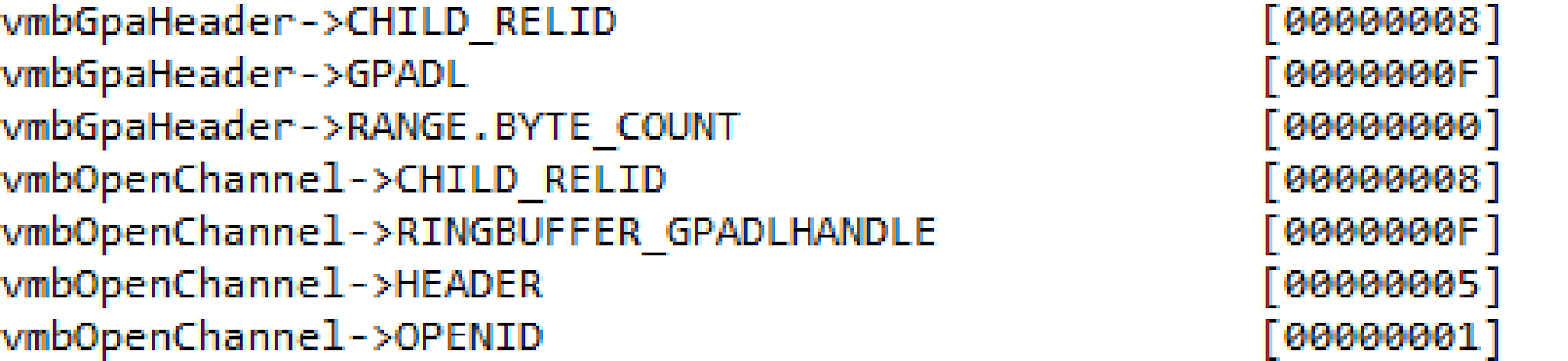
The first 16 bytes - this is a common header message where 0xF0 - the size of the message body. VMBus-packet placed inside, header of that VMBus packet indicates the type of package - 8 (CHANNELMSG_GPADL_HEADER), rangecount is 1 which means that in one package together all the data have been transmitted. Next the root OS sends message CHANNELMSG_OPENCHANNEL_RESULT, then the guest OS sends CHANNELMSG_OPENCHANNEL. After that, the root OS fulfills the Work Items
WINDBG>kc
Call Site
vmbusr!ChMapGpadlView
vmbkmclr!KmclpServerOpenChannel
vmbkmclr!KmclpWaitForActionWorkerRoutine
nt!IopProcessWorkItem
nt!ExpWorkerThread
nt!PspSystemThreadStartup
nt!KiStartSystemThread
in the execution of which is called vmbusr!ChMapGpadlView, from which there comes a call of vmbusr!PkParseGpaRanges, which has a parameter - pointer of part of the message, which contains the size of the buffer 0xC000 and pfn, passing in CHANNELMSG_GPADL_HEADER message. Next call vmbusr!XPartLockChildPagesSynchronous-> vmbusr! XPartLockChildPages and then the function of the driver vid.sys (the name of the function is unknown, because there are no symbols for this driver), where as 2-th parameter is the block of pfn passed as message from the guest OS
WINDBG>u @rip – the beginning of an unnamed function from vid.sys
Vid+0x18000:
fffff800`7d218000 xor r11d,r11d
fffff800`7d218003 mov r10,rcx
fffff800`7d218006 cmp r9d,1
fffff800`7d21800a je Vid+0x1804a (fffff800`7d21804a)
fffff800`7d21800c lea eax,[r11+1]
fffff800`7d218010 mov rcx,qword ptr [rsp+28h]
fffff800`7d218015 mov dword ptr [rcx+2Ch],eax
fffff800`7d218018 mov rax,qword ptr [rsp+38h]
WINDBG>dd poi(@rdx)
ffffe001`ae827210 0000c000 00000000 0002d5bb 00000000
ffffe001`ae827220 0002d5bc 00000000 0002d5bd 00000000
ffffe001`ae827230 0002d5be 00000000 0002d5bf 00000000
ffffe001`ae827240 0002d5c0 00000000 0002d5c1 00000000
ffffe001`ae827250 0002d5c2 00000000 0002d5c3 00000000
ffffe001`ae827260 0002d5c4 00000000 0002d5c5 00000000
ffffe001`ae827270 0002d5c6 00000000 00065d63 00000000
immediately after the return from the function in [rsp+30h] is a pointer to the new MDL:

Next mdl contains the pfn of root OS.

WINDBG>dd 0xffffe001`ae827180
ffffe001`ae827180 00000000 00000000 00020090 ffffe001
ffffe001`ae827190 ab49f900 ffffe001 00000000 00000000
ffffe001`ae8271a0 00000000 00000000 0000c000 00000000
ffffe001`ae8271b0 001367bb 00000000 001367bc 00000000
ffffe001`ae8271c0 001367bd 00000000 001367be 00000000
ffffe001`ae8271d0 001367bf 00000000 001367c0 00000000
ffffe001`ae8271e0 001367c1 00000000 001367c2 00000000
ffffe001`ae8271f0 001367c3 00000000 001367c4 00000000
after this the root OS sends CHANNELMSG_OPENCHANNEL_RESULT message. On that the process activation components Data Exchange is finished. Result is a creation of shared-buffer, visible for the guest and root OS. You can verify this by running a record arbitrary bytes in the buffer inside the guest OS, for example by using the command:
WINDBG>!ed 2d5bb000 aaaaaaaa
WINDBG>!db 2d5bb000
#2d5bb000 aa aa aa aa 10 19 00
in the root OS you can see the page content, of the pfn returned function of the driver vid.sys:
WINDBG>!db 1367bb000
#1367bb000 aa aa aa aa 10 19
As you can see that the values match, so it's really the same physical memory area, which guest and the root OS uses.
Recall that in the previous stages we define that when the feature Data Exchange is activated and it creates a port of the type HvPortTypeEvent with TargetSint = 5. Accordingly all operations with this port in the root OS will handle by KiVmbusInterrupt1, from which it calls vmbusr!XPartEnlightenedIsr, which calls KeInsertQueueDpc with the DPC, containing:
WINDBG>dt _KDPC @rcx
PSHED!_KDPC
+0x000 TargetInfoAsUlong : 0x113
+0x000 Type : 0x13 ''
+0x001 Importance : 0x1 ''
+0x002 Number : 0
+0x008 DpcListEntry : _SINGLE_LIST_ENTRY
+0x010 ProcessorHistory : 1
+0x018 DeferredRoutine : 0xfffff800`08003de0 void vmbusr!ParentRingInterruptDpc+0
+0x020 DeferredContext : 0xfffff800`080130e0 Void (vmbusr!XPartLibContextStatic)
+0x028 SystemArgument1 : (null)
+0x030 SystemArgument2 : (null)
+0x038 DpcData : (null)
vmbusr!ParentRingInterruptDpc calls vmbusr!PkGetReceiveBuffer:
WINDBG>k
Child-SP RetAddr Call Site
fffff800`fcc1ea38 fffff800`6cdc440c vmbusr!PkGetReceiveBuffer+0x2c
fffff800`fcc1ea40 fffff800`6cdc41a7 vmbusr!PipeTryReadSingle+0x3c
fffff800`fcc1eaa0 fffff800`6cdc4037 vmbusr!PipeProcessDeferredReadWrite+0xe7
fffff800`fcc1eaf0 fffff800`6c96535e vmbusr!PipeEvtChannelSignalArrived+0x63
fffff800`fcc1eb30 fffff800`6cdc4e3d vmbkmclr!KmclpVmbusManualIsr+0x16
fffff800`fcc1eb60 fffff800`fb2d31e0 vmbusr!ParentRingInterruptDpc+0x5d
Put a breakpoint on the function vmbusr!PkGetReceiveBuffer and run our powershell script. The breakpoint will trigger and you will see that the function is passed with a structure (a pointer to the rcx) in rcx +18 is a pointer to the memory block:
WINDBG>? poi(@rcx+18)
Evaluate expression: -52770386006016 = ffffd001`6fe33000
WINDBG>!pte ffffd001`6fe33000
VA ffffd0016fe33000
PXE at FFFFF6FB7DBEDD00 PPE at FFFFF6FB7DBA0028 PDE at FFFFF6FB74005BF8 PTE at FFFFF6E800B7F198
contains 0000000000225863 contains 00000000003B7863 contains 000000010FB12863 contains 80000001367BB963
pfn 225 ---DA--KWEV pfn 3b7 ---DA--KWEV pfn 10fb12 ---DA--KWEV pfn 1367bb -G-DA--KW-V
WINDBG>r cr3
cr3=00000000001ab000
WINDBG>!vtop 1ab000 ffffd0016fe33000
Amd64VtoP: Virt ffffd001`6fe33000, pagedir 1ab000
Amd64VtoP: PML4E 1abd00
Amd64VtoP: PDPE 225028
Amd64VtoP: PDE 3b7bf8
Amd64VtoP: PTE 00000001`0fb12198
Amd64VtoP: Mapped phys 00000001`367bb000
Virtual address ffffd0016fe33000 translates to physical address 1367bb000.
If you view this memory area the guest OS options are visible.
WINDBG> dc ffffd0016fe33000 L1000
…………………………………………………………………………………………………………………
ffffd001`6fe35b30 0065004e 00770074 0072006f 0041006b N.e.t.w.o.r.k.A.
ffffd001`6fe35b40 00640064 00650072 00730073 00500049 d.d.r.e.s.s.I.P.
ffffd001`6fe35b50 00340076 00000000 00000000 00000000 v.4.............
…………………………………………………………………………………………………………………
ffffd001`6fe35d20 00000000 00000000 00000000 00000000 ................
ffffd001`6fe35d30 00300031 0030002e 0030002e 0033002e 1.0...0...0...3.
ffffd001`6fe35d40 00000000 00000000 00000000 00000000 ................
WINDBG>!pte ffffd001`6fe35b30
VA ffffd0016fe35b30
PXE at FFFFF6FB7DBEDD00 PPE at FFFFF6FB7DBA0028 PDE at FFFFF6FB74005BF8 PTE at FFFFF6E800B7F1A8
contains 0000000000225863 contains 00000000003B7863 contains 000000010FB12863 contains 80000001367BD963
pfn 225 ---DA--KWEV pfn 3b7 ---DA--KWEV pfn 10fb12 ---DA--KWEV pfn 1367bd -G-DA--KW-V
pfn 1367bd – is a pfn 3-th page of the converted MDL.
Also the same function in rdx is a pointer that contains the offset of the starting address shared with the guest OS pages (in the example it is 4448h) that you want to read:
vmbusr!PkGetReceiveBuffer+0x4e:
mov r8,r10 (in r10d was previously loaded displacement of rdx)
add r8,qword ptr [rcx+20h] – the rcx+20 contains a pointer to one of the guest OS pages
WINDBG>!pte @r8
VA ffffd0016ff22448
PXE at FFFFF6FB7DBEDD00 PPE at FFFFF6FB7DBA0028 PDE at FFFFF6FB74005BF8 PTE at FFFFF6E800B7F910
contains 0000000000225863 contains 00000000003B7863 contains 000000010FB12863 contains 80000001367C0963
pfn 225 ---DA--KWEV pfn 3b7 ---DA--KWEV pfn 10fb12 ---DA--KWEV pfn 1367c0 -G-DA--KW-V
If you set a breakpoint on the instruction add r8,qword ptr [rcx+20h] then follow through several iterations in r8 you can see:
WINDBG>dc @r8
ffffd001`6ff21d10 00020006 00000148 00000000 00000000 ....H...........
ffffd001`6ff21d20 00000001 00000a28 00000003 00050002 ....(........... - Transmission Unit
ffffd001`6ff21d30 0a140000 00000000 00000515 00000103 ................
ffffd001`6ff21d40 00000004 00000001 00000016 0000001a ................
ffffd001`6ff21d50 0076004b 00440050 00740061 004b0061 K.v.P.D.a.t.a.K.
ffffd001`6ff21d60 00790065 00000000 00000000 00000000 e.y.............
ffffd001`6ff21d70 00000000 00000000 00000000 00000000 ................
ffffd001`6ff21d80 00000000 00000000 00000000 00000000 ................
………………………………………………………………………………………………………………….
ffffd001`6ff21f40 00000000 00000000 00000000 00000000 ................
ffffd001`6ff21f50 0076004b 00440050 00740061 00560061 K.v.P.D.a.t.a.V.
ffffd001`6ff21f60 006c0061 00650075 00000000 00000000 a.l.u.e.........
ffffd001`6ff21f70 00000000 00000000 00000000 00000000 ................
WINDBG>!pte ffffd001`6ff21f50
VA ffffd0016ff21f50
PXE at FFFFF6FB7DBEDD00 PPE at FFFFF6FB7DBA0028 PDE at FFFFF6FB74005BF8 PTE at FFFFF6E800B7F908
contains 0000000000225863 contains 00000000003B7863 contains 000000010FB12863 contains 80000001367BF963
pfn 225 ---DA--KWEV pfn 3b7 ---DA--KWEV pfn 10fb12 ---DA--KWEV pfn 1367bf -G-DA--KW-V
then after the completion of the PkGetReceiveBuffer function PipeTryReadSingle copies the data from the shared-buffer using memmove. The block size (in this case A28) is specified directly in the block, but if the number is greater than 4000h the copying is not performed. Thus it is seen that the exchange of data between the root OS and the guest OS uses a shared buffer, and the interface of hypervisor is used only to notify the root OS that the data must be read from this buffer. In principle, the same operation could be done by sending multiple messages using winhv!HvPostMessage, but this would lead to a significant performance degradation.
2.The use of the interception interface
Configure a hypervisor to send notification to root OS in case if one of the guest OS executes cpuid with the 0x11114444. For this hyper-v provides an interface in the form of an hypercall HvInstallIntercept. There is function SetupIntercept In hyperv4 driver, which takes a list of identifiers of all active guest operating systems and calls for each one WinHvInstallIntercept.
int SetupIntercept()
{
HV_INTERCEPT_DESCRIPTOR Descriptor;
HV_INTERCEPT_PARAMETERS Parameters = {0};
HV_STATUS hvStatus = 0;
HV_PARTITION_ID PartID = 0x0, NextPartID = 0;
// If the instructions in rax contains the cpuid instruction the value 0x11114444 will be passed, // the hypervisor will intercept and send the message to the parent section to process the result DbgPrintString("SetupInterception was called");
Parameters.CpuidIndex = 0x11114444;
Descriptor.Type = HvInterceptTypeX64Cpuid;
Descriptor.Parameters = Parameters;
hvStatus = WinHvGetPartitionId(&PartID);
do{
hvStatus = WinHvGetNextChildPartition(PartID, NextPartID, &NextPartID);
if (NextPartID != 0){
DbgLog("Child partition id", NextPartID);
hvStatus = WinHvInstallIntercept(NextPartID, HV_INTERCEPT_ACCESS_MASK_EXECUTE, &Descriptor);
DbgLog("hvstatus of WinHvInstallIntercept = ", hvStatus);
}
} while ((NextPartID != HV_PARTITION_ID_INVALID) && (hvStatus == 0));
return 0;
}
Also change the PrintCpuidInterceptMessage so that it is in the case, if the guest OS EAX register (or RAX, if the code executes instructions CPUID is performed in longmode) contains the number 0x11114444, it is recorded in the field DefaultResultRdx of structure HV_X64_CPUID_INTERCEPT_MESSAGE which is located in the zero slot SIM with, the value of 0x12345678:
void PrintCpuidInterceptMessage(PHV_MESSAGE hvMessage)
{
PHV_X64_CPUID_INTERCEPT_MESSAGE phvCPUID = (PHV_X64_CPUID_INTERCEPT_MESSAGE)hvMessage->Payload;
DbgLog(" phvCPUID->DefaultResultRax", phvCPUID->DefaultResultRax);
DbgLog(" phvCPUID->DefaultResultRbx", phvCPUID->DefaultResultRbx);
DbgLog(" phvCPUID->DefaultResultRcx", phvCPUID->DefaultResultRcx);
DbgLog(" phvCPUID->DefaultResultRdx", phvCPUID->DefaultResultRdx);
if (phvCPUID->Rax == 0x11114444){
phvCPUID->DefaultResultRdx = 0x12345678;
DbgLog16(" phvCPUID->Header.Rip", phvCPUID->Header.Rip);
DbgPrintString(" Interception was handled");
}
}
To check the guest operating system to run the test utility, which causes cpuid with eax, equal to 0x11114444. Before installing the utility displays for the result of the interception:
After activating the capture result are:
With this in WINDOWS root it will display a message

Immediately notice that this trick will take place only if the root OS does not find interceptions for the specified conditions and If the root OS previously didn´t find interceptions for the specified conditions. In this case, after the hyperv4 driver will replace the value and control is passed back to the original WinHvOnInterrupt, which will cause the processing of driver vid.sys (his function is the fourth parameter to winhvr! WinHvCreatePartition, called in the root operating system to create the child partition when the virtual machine loads) that will lead to a different result. In our case is such a handler of course not installed, the hypervisor has been analysed data in the SIM0 and fixed the result of the CPUID instruction.
In conclusion, I will say that the article is rather a review demonstrating some virtualization features and components that examples Microsoft, however I hope these examples will help you get a better understanding for these components and allows you for a more detailed analysis of their safety.
Files: https://drive.google.com/file/d/0B8WEjIxRncDRUVFLWGhXN0xDMHc
Files: https://drive.google.com/file/d/0B8WEjIxRncDRUVFLWGhXN0xDMHc
Gerhart